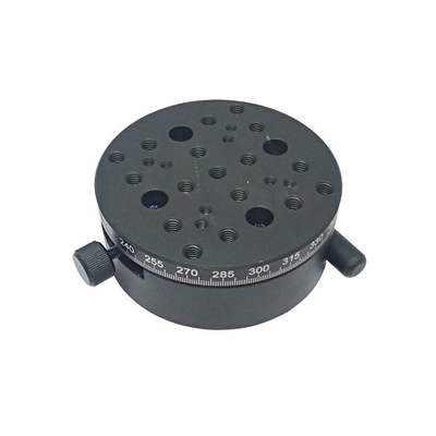
Optical Sliding Table , R Axis Manual Rotation Stage, Rotating Platform PT-SD206
Precision manual rotary table: PT-SD206
Product features:
■ the table can be rotated 360 ° for rough adjustment.
■ fine adjustment of ± 10 °, micrometer head drive, spring return, high resolution and no empty return.
■ precision shafting design, adjustable shafting clearance and stability.
■ 360 ° laser marking around the circumference for easy reading.
■ there are connecting holes with standard hole spacing at the upper and lower parts, which is convenient to connect with other displacement tables to form a multi-dimensional mobile table.
Product parameters:
|
Item Number
|
PT-SD206 |
|
Rotation Range
|
coarse 360° fine ±10° |
|
Diameter of Platform:
|
Ø82mm |
|
Actuator Type
|
Micrometer Head in Side |
|
Graduations
|
1° |
|
Minimum Readout
|
2' |
| Minimum Adjust Distance |
15" |
|
Surface Roundness
|
60μm |
| Transversal Deviation |
30μm |
|
Parallelism
|
60μm |
|
Material – Finish
|
Aluminum Alloy - Black-Anodized |
|
Load Capacity
|
5Kgs |
|
Weight
|
0.5kgs |
Product Dimension Map:

Rotary table center correction
The purpose is to make the vertical axis of the rotating table coincide with the microscope axis. Move the sheet so that a small mineral particle (hereinafter referred to as particle) is placed on the crosshair intersection, each axis is at the zero position, and the stage is locked at 0 °.
Rotate the n-axis 360 °, if the particle makes a circular motion around the center of the crosshair, it indicates that the center is not correct and needs to be corrected. The principle of the method is the same as that of the correction of the objective lens center of the microscope. Rotate the n-axis 180 °, and the particle is the farthest from the center. Gently rotate the two correction screws of the additional chassis (if there is no such chassis, gently push the base that has not been locked with both hands), move the particle to half the center of the crosshair, and move the sheet by hand to place the original particle or another particle in the center of the field of view.
Turn the n-axis inspection again. If the particle still moves away from the center of the crosshair, adjust the correction screw of the rotating table (or move the base) again until the particle in the field of view center does not deviate from the center of the crosshair during the n-axis inspection. For the rotary table without additional chassis, be sure to lock the base fixing screw at this time.

 Your message must be between 20-3,000 characters!
 Please check your E-mail!
  Your message must be between 20-3,000 characters!
 Please check your E-mail!


